3D Printing
3D printing is used to create custom cutting molds from 7T MRI scans. Prerequisites for this step are
A 7T scan of the whole MTL sample copied to your working computer.
Completed ITK-SNAP training from itksnap.org/rsna2017
Install ITKSNAP and C3D and MeshLab
Step 1. Convert 7T scan to NIFTI
Locate the folder containing the 7T scan.
Create a work folder where the holder creation will take place
Open the 7T DICOM image in ITK-SNAP
Be sure to select series that does not end with “_ND” (no distortion)
Save the image in the work folder as mtl7t.nii.gz
Step 2. Segment the MTL from background in ITK-SNAP
Load mtl7t.nii.gz into ITK-SNAP
Enter the automatic (snake) segmentation mode
If you want to change the resolution of the image to make the program go faster, after clicking on the automatic segmentation button, click “Resample ROI” under within the inspect box
When you hit “Segment 3D”, click on “Presets” and choose “Subsample by 2”
This will increase the voxel size, making the segmentation rougher but faster
Enter “classification” pre-segmentation mode
Label the tissue as “red” label, and background (fomblin) as “green” label
If there is some water on top of the sample, label it with another label
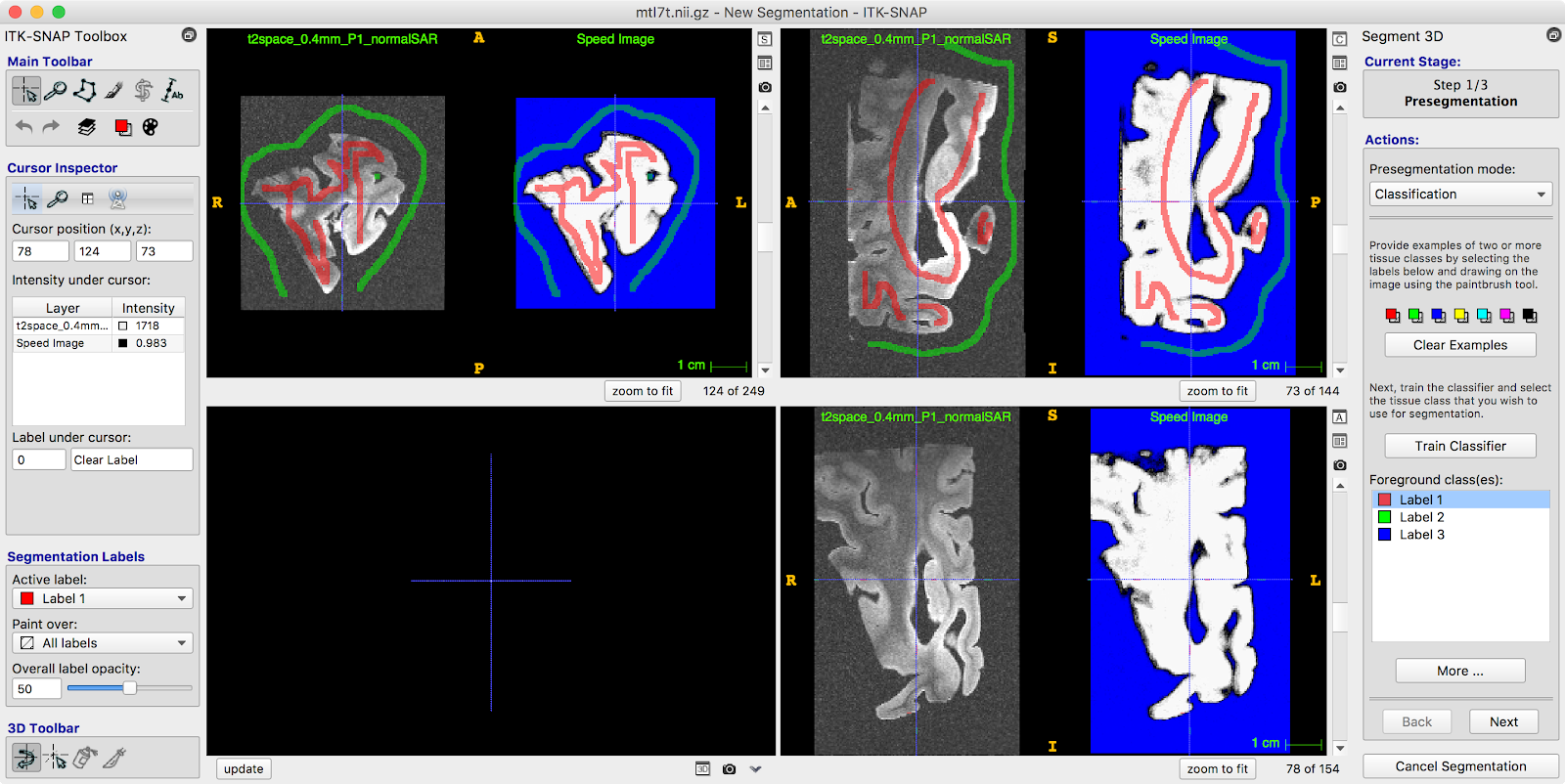
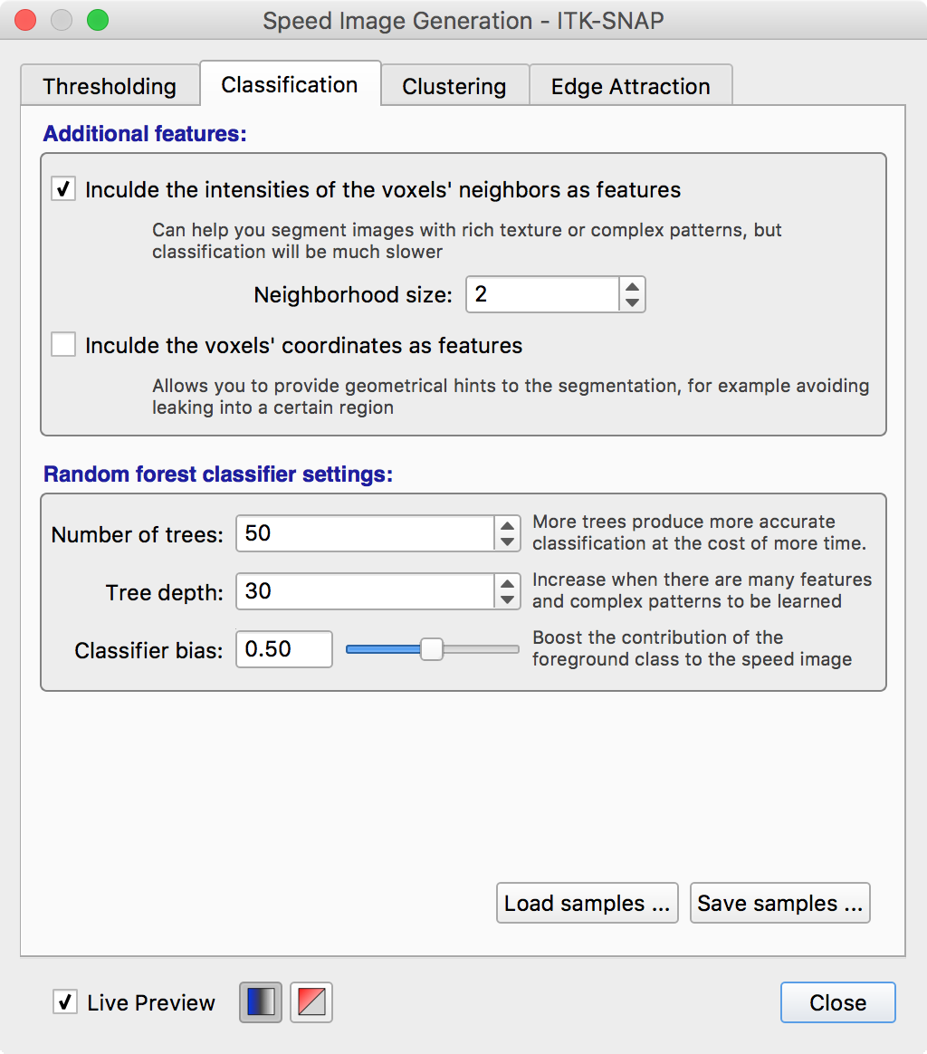
Under “More…” set the “Neighborhood size” to 2
Very carefully train the classifier to isolate foreground from background
Keep adding training samples at places where the classifier
messes up
Save the classifier training samples as “training_samples.nii.gz”
This option is on the More…
Add bubbles and run contour (snake) evolution. Verify that the segmentation is good.
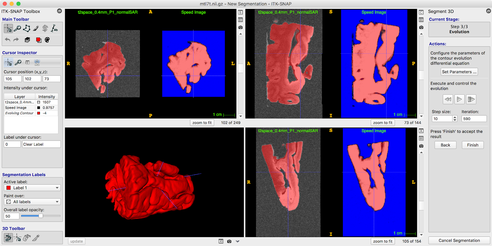
Before clicking “Finish”, click “Layer Inspector…” (Tools -> Layer Inspector…) and save the “**evolving contour” **layer as “contour_image.nii.gz”
Exit the segmentation mode. You do not need to save the actual segmentation.
Step 3. Create a reference mold
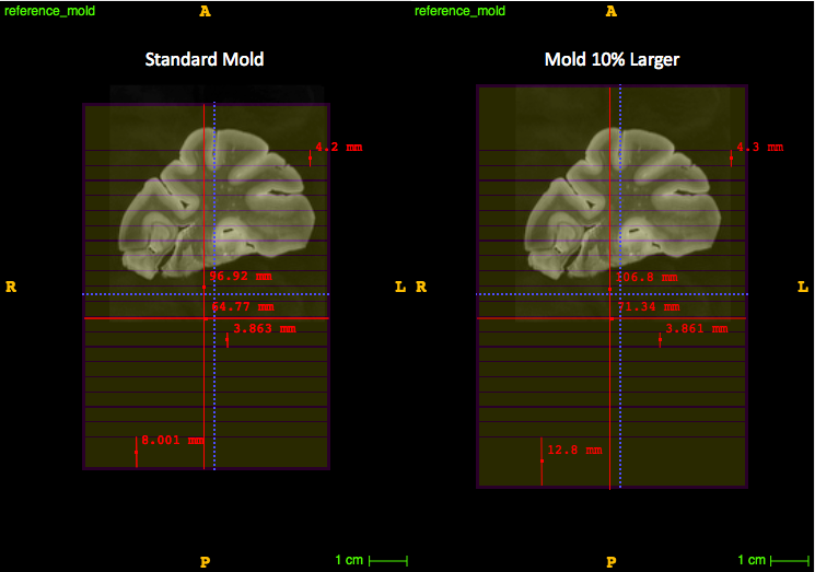
The reference mold is a 3D image that looks like a brick with slits for cutting. The actual mold will be carved out of the reference mold.
Open a terminal
Change directory to your work directory
The reference mold is created using the following C3D command:
a. The first script is for a standard size sample
b. The second script is for a larger sample (10% larger mold). Try the first script, if the MTL cannot be rotated correctly in that mold use the larger reference mold.
c3d -create 320x480x320 0.2x0.2x0.2mm -orient LPI -origin-voxel 50% \\
-cmp -popas z -popas y -popas x \\
-push y -scale 1.570796 -cos -acos -scale 0.318310 -thresh -inf 0.1 -4 4 \\
-push z -thresh -inf -28 4 -4 -max -push y -thresh -40 40 -4 4 -max \\
-pad 5x5x5 5x5x5 -4 -o reference\_mold.nii.gz

c3d -create 352x528x352 0.2x0.2x0.2mm -orient LPI -origin-voxel 50% \\
-cmp -popas z -popas y -popas x \\
-push y -scale 1.570796 -cos -acos -scale 0.318310 -thresh -inf 0.1 -4 4 \\
-push z -thresh -inf -28 4 -4 -max -push y -thresh -50 50 -4 4 -max \\
-pad 5x5x5 5x5x5 -4 -o reference\_mold.nii.gz

c3d -create 384x576x384 0.2x0.2x0.2mm -orient LPI -origin-voxel 50% \\
-cmp -popas z -popas y -popas x \\
-push y -scale 1.570796 -cos -acos -scale 0.318310 -thresh -inf 0.1 -4 4 \\
-push z -thresh -inf -28 4 -4 -max -push y -thresh -60 60 -4 4 -max \\
-pad 5x5x5 5x5x5 -4 -o reference\_mold.nii.gz
FOR FRONTAL LOBES:
c3d -create 460x775x460 0.2x0.2x0.2mm -orient LPI -origin-voxel 50% \\
-cmp -popas z -popas y -popas x \\
-push y -scale 1.570796 -cos -acos -scale 0.318310 -thresh -inf 0.1 -4 4 \\
-push z -thresh -inf -28 4 -4 -max -push y -thresh -70 70 -4 4 -max \\
-pad 5x5x5 5x5x5 -4 -o reference\_mold.nii.gz
NOTE: To change the number of slits in the y direction change the “-40 40” line (ex. In the 20% larger mold more slits were added by changing it to “-50 50”). To change the depth of the slits alter the “-28” in the z direction.
Step 4. Find the correct rotation of the 7T image
This step finds the main axis of the hippocampus and aligns it with one of the canonical axes of the image. This allows the cutting mold to follow the main axis of the hippocampus.
Load
reference_mold.nii.gzas the main image in ITK-SNAPAssign the Spring color map to the reference mold
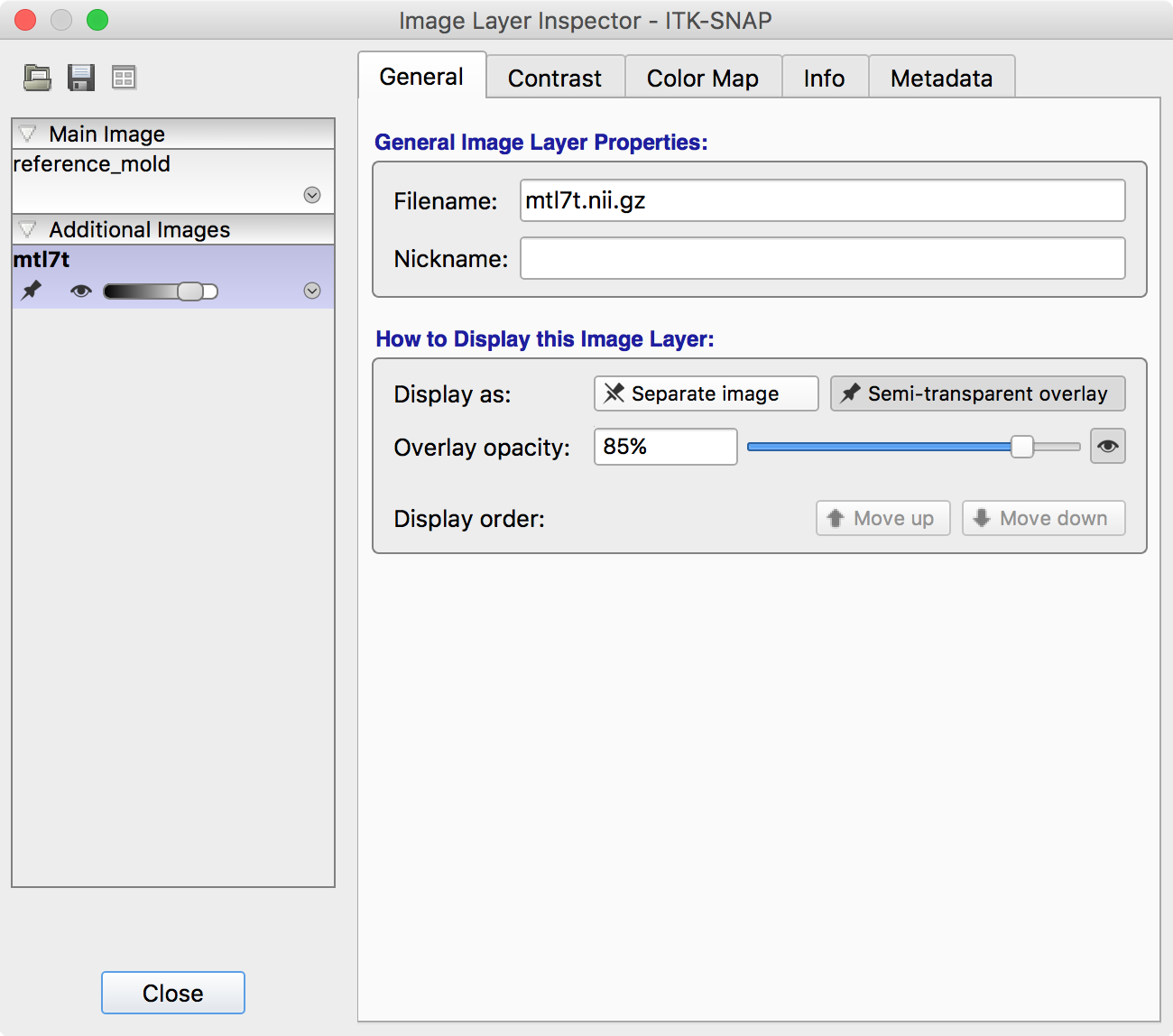
Load
mtl7t.nii.gzas the overlay image usingFile->Add Another Image.Click “As a semi-transparent overlay”
Enter registration mode (
Tools->Registration) and go to the Manual tabDisplay the MRI scan as a semi-opaque overlay
Tools->Layer InspectorSelect the MRI layer
Go to the General tab
Click Display as semi-transparent overlay and set opacity to 85%
Rotate and translate the MRI so that the sample is positioned well in the reference mold. This may require some practice to get right. Here are the general rules to follow:
The tissue should be inside the “slitted” region of the reference mold. In other words, the bottom of the tissue should be above the line where the slits begin.
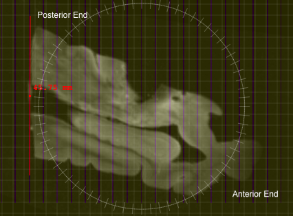
The hippocampal main axis should be aligned with the A-P axis, but rotated so that the posterior end of the MTL is parallel to the slits in the mold
This is with the assumption that during hemisphere cutting, the posterior end of the hemisphere is cut at an angle that is parallel to the AC-PC line, so that when you align the slits with the posterior end, the MTL will be cut perpendicular to the AC-PC line
When looking at the coronal view, find a slice in the MRI where the tissue looks to be the largest, and measure the tissue to ensure that the largest portions of the tissue would fit on a 75mm x 50mm glass slide (2”x3” slide)
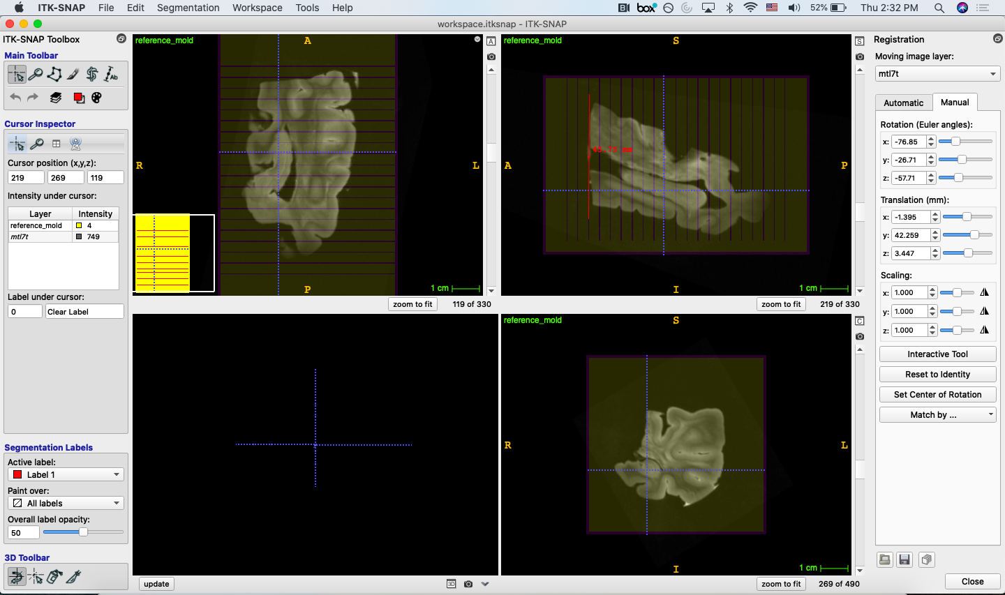
The tissue should be centered in the mold on the L-R axis and A-P axis
When satisfied use the floppy disk icon to save your registration as
holderrotation.matMake sure under format, “Convert3D Transform File” is selected
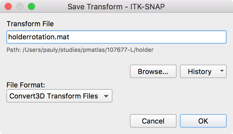
Save your workspace as
workspace.itksnap
Step 5. Carve the tissue segmentation out of the mold
This command carves out the tissue segmentation out of the mold. It generates an image that is positive inside the plastic mold and negative in the air.
c3d reference\_mold.nii.gz -as R contour\_image.nii.gz -background 4 \\
-reslice-matrix holderrotation.mat \\
-swapdim IPL -extrude-seg -swapdim LPI \\
-push R -min -o slitmold.nii.gz
Trim the mold in ITK-SNAP
Open
slitmold.nii.gzin a new ITK-SNAP windowLoad
mtl7t.nii.gzas an additional imageEnter registration mode and use the open icon to load
holderrotation.matUse the Crosshairs tool to position the cursor (horizontal blue line in the top right view in picture below) slightly superior to the top of the sample
Click the Polygon tool and draw around the tissue but leaving out excess plastic:
i. Once polygon is drawn, click accept
ii. Use Crosshairs tool again to position the cursor (same horizontal blue line) slightly below the bottom of the holder
iii. Click the Polygon tool again, then click “paste last polygon” to draw the identical polygon in that slice
iv. Click accept again
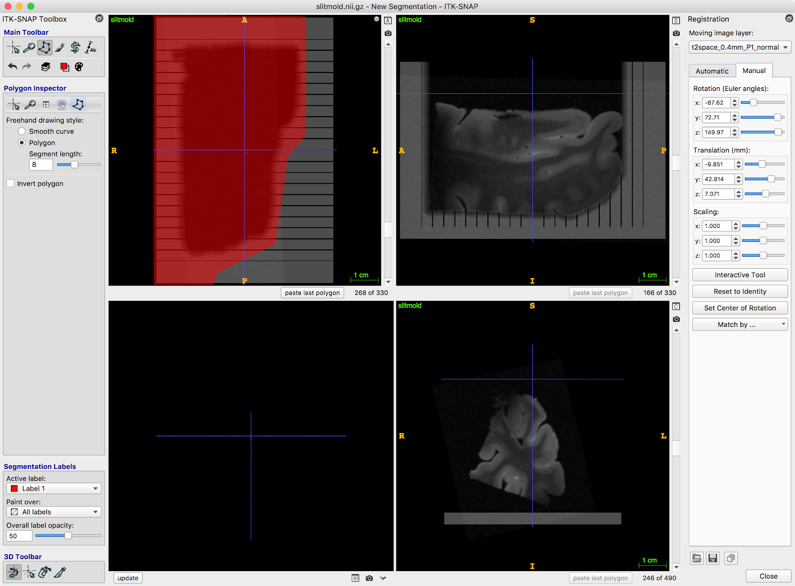
Interpolate between these polygons using
Tools->Interpolate LabelsSave the segmentation as
cropmask.nii.gzRun following command to crop the block:
c3d cropmask.nii.gz -pad 4x4x4 4x4x4 0 \\
-stretch 0 1 -4 4 -dup slitmold.nii.gz \\
-reslice-identity -min -o slitmold\_cropped.nii.gz
Step 6. Generate Surface Mesh of the Mold
This command generates a 3D surface mesh from the image above
vtklevelset slitmold_cropped.nii.gz slitmold.stl 0.0
OR if
vtklevelsetis not in your/usr/local/bin:Type
PATH=$PATH:/path/to/directory/binbefore the command (change/path/to/directory/binto the path to the folder containing thevtklevelsetexecutable)PATH=$PATH:/Applications/ITK-SNAP.app/Contents/bin/ vtklevelset slitmold_cropped.nii.gz slitmold.stl 0.0
Step 7. Simplify the STL file for 3D printing
Run Meshlab and load
slitmold.stlusingFile->Import MeshGo to
Filters->Remeshing->Quadric Edge Collapse DecimationSet options as recommended below:
Percentage reduction:        0.1
Preserve boundary:           checked
Preserve normal:             checked
Preserve topology:           checked
Optimal position:            checked
Planar simplification:       checked
Post-simplification:         checked
Hit apply
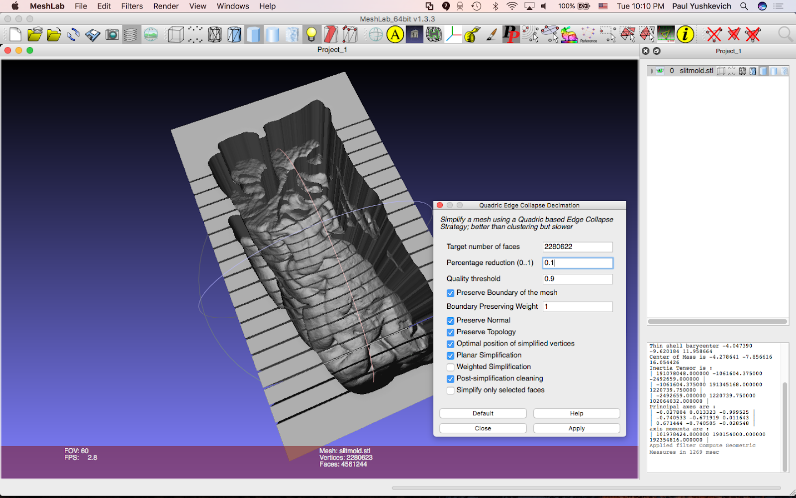
The simplified mesh should be visually similar to the input mesh, but will have 90% fewer faces.
Export mesh as
slitmold_reduced.stl(usingFile->Export Mesh As)This mesh should be sent to the 3D printer
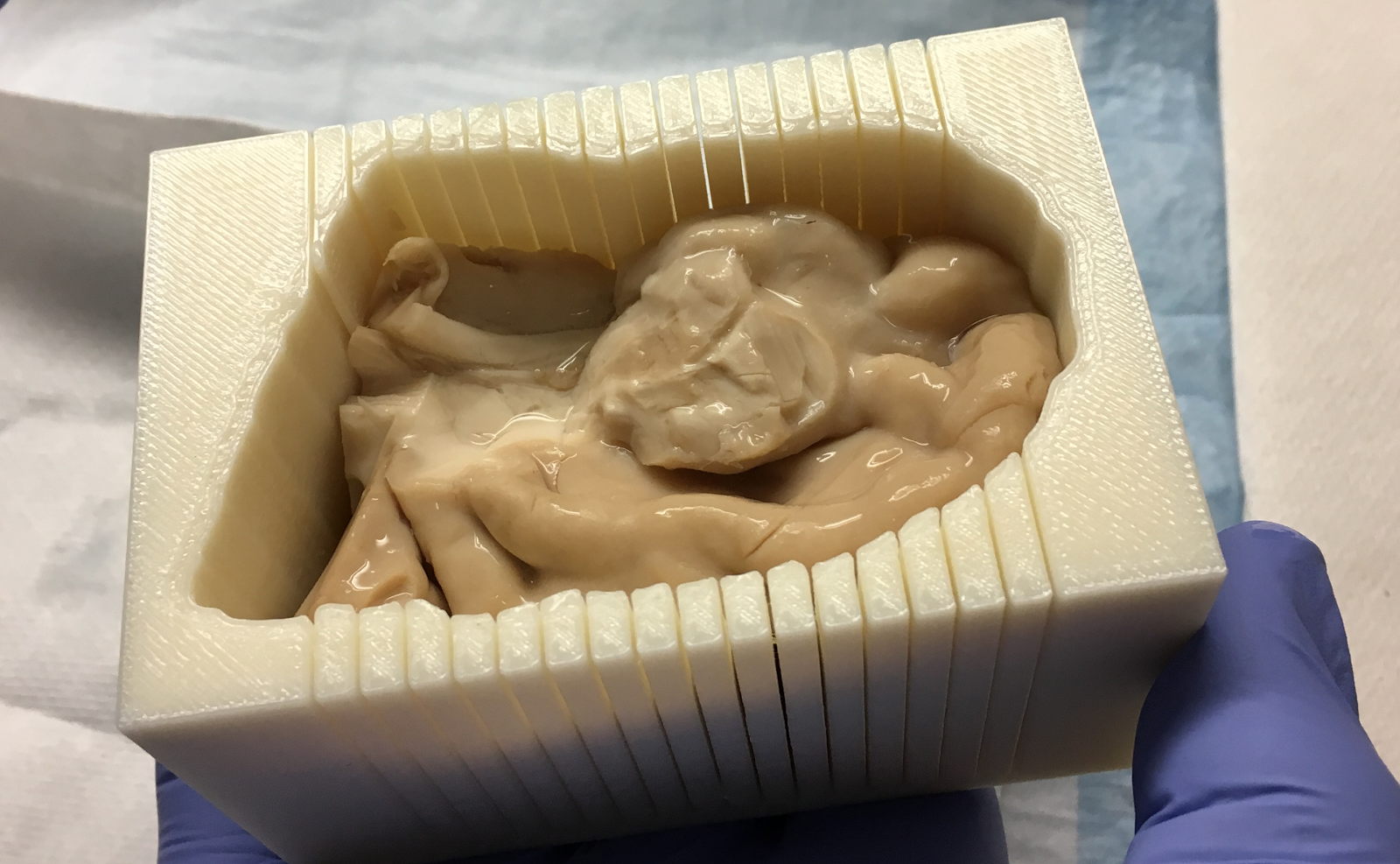
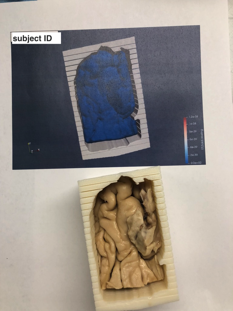
Step 8. Visualize mold and tissue in ParaView
This step helps you see the angle at which the sample should be placed in the mold.
These commands extract an STL mesh of the sample itself.
c3d slitmold_cropped.nii.gz contour_image.nii.gz \\
    -reslice-matrix holderrotation.mat \\
    -o contour_image_rotated.nii.gz

vtklevelset contour_image_rotated.nii.gz sample_inplace_mesh.stl 0.0
Open the meshes
slitmold_reduced.stlandsample_inplace_mesh.stlin ParaViewTake a screenshot of the sample in the mold.
[UPENN Only]: Add this image to the running document of images here with a sample ID label: https://upenn.box.com/s/wbzn5rjkkud48s82kwtrac9ms48nf3qg
Print the image, and use to guide placement of tissue in the mold